This is a summary note of the course “Computer Organization and Architecture” by Professor William Stallings.
The remaining contents are organized as:
- Chapter 14
- Processor Organization
- Register Organization
- Instruction Cycle
- Pipelining
Chapter 14: Processor Structure and Function
Processor Organization
First consider the requirements of the processor (or CPU, Central Processing Unit).
- Fetch Instruction (FI)
- Interpret Instruction (DI)
- Fetch Data (FO)
- Process Data (CO, EI)
- Write Data (WO)
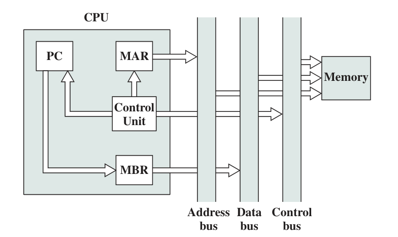
A processor builds interconnection with system bus. Typically, it contains Control Bus, Data Bus, and Address Bus. Inside the CPU, there are Registers, ALU, and Control Unit with control paths and a Internal Processor Bus to construct interconnection.
Register Organization
At higher levels of the hierarchy, memory is faster, smaller, and more expensive - From Memory Hierarchy.
Registers are temporal storage in the processor. The level of register is higher than main memory and cache. There are mainly two register roles in the processor:
User Visible Registers
Registers that enable machine or programmer to deploy in order to minimize the main memory references.
There are four main types of user-visible registers (however they are not clearly seperated):
- General Purpose (通用寄存器)
- Address
- Data
- Condition Codes, or flags
True General-purpose regs contain any operand for any opcode. However in most cases these regs are dedicated to floating-point regs or stack regs. The number of GP regs range from 8 to 32.
- Fewer number of GP regs increases memory references
- More GP regs doesn’t reduce memory referfences and take up more processor real estate(占用空间)
Data regs only hold data, while cannot be referenced in calculation of the address.
Address regs may be devoted to a specific address mode, which can be catagorized as:
- Stack pointer (For Stack Addressing)
- Index register (For Autoindexing or Index addressing)
- Segment Pointers (For system with segments)
Condition Codes are set of individual bits. They usually cannot be modified by programs.
Typical condition codes include:
- Sign
- Zero Flag
- Carry Flag
- Equal
- Overflow
- Interrupt Enable
- Supervisor: Allows privileged instructions to execute, not available to user programs
- etc.
They are more often appeared in PSWs.
Pros and Cons:
| Advantages | Disadvantages |
|---|---|
Reduced the number of Compare or TEST Commands |
Add complexity to hardware and software |
| Conditional instructions are simplified | Require additional hdw connection |
| Easy to implement multiple branches | Need additional conditional-code-support instruction |
| Can be saved on stack | In pipelined implementation, it needs extra sync process |
The register size is designed to hold a full address or word considering its type. Computers often permits combining two registers as one to use, such as type long long and long double.
Control and Status Registers
Used by Control Unit to control the behavior of the processor, and by privileged operating system to control the execution of programs.
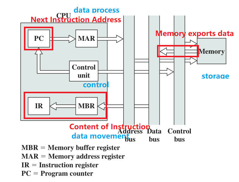
- PC: Program Counter, point to the address of next instruction.
- IR: Instruction Register, contains instruction, not connected to any bus
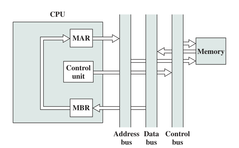
- MAR: Memory Address Register, contains memory address, connected to address bus
-
MBR: Memory Buffer Register, contains data, connected to data bus
- Program Status Word (PSW): A or a set of regs containing status information involving condition code
Instruction Cycle
A instruction cycle includes:
- Fetch
- Execute
- Interrupt
- Indirect
They are not sequentially organized, but interconnected.
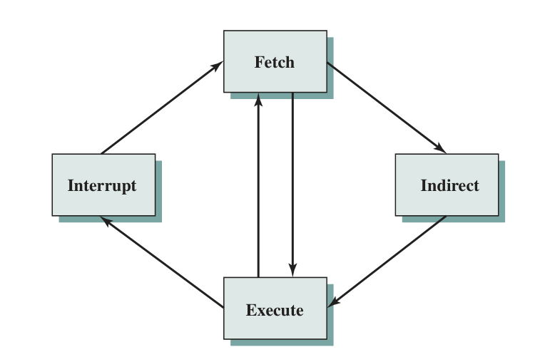
In actual instruction cycle, there will be an interruption check during operand storage and next instruction fetch process in the diagram below.
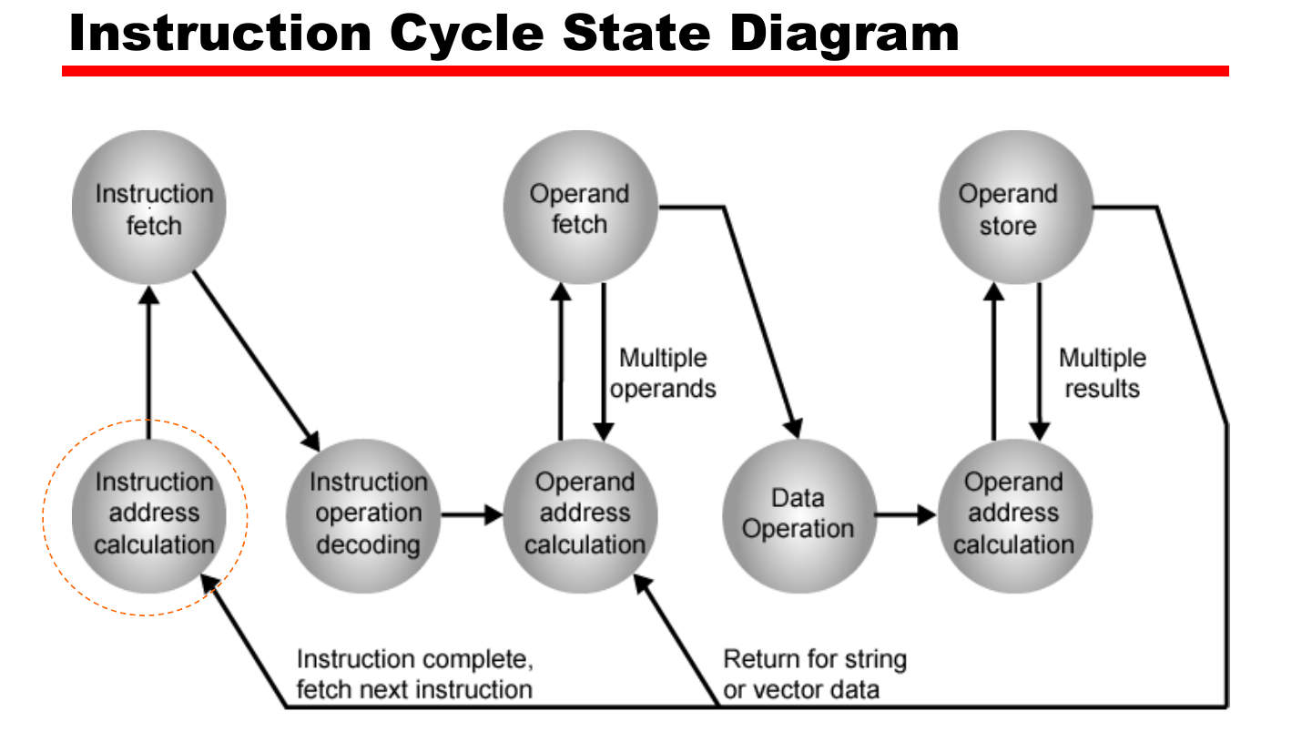
Data flow
In this part we will show the data flow of Fetch, Indirect and Interrupt process, as execution process requires no data flow in the processor.
Fetch Process Data flow are described below.
Indirect Process Data flow are described below.
Interrupt Process Data flow are described below.
Pipelining
Six-stage pipeline for CPU
Here’s a six-stage pipelined CPU operating diagram. Note that unconditional branch refers to operations like JMP AX which require no full instruction operated. Branches and Interrupts can contain conditions, like JNZ AX.

Every pipeline flush occurs after the CO or EI process has been done.
Pipeline performance
Two main factors: Time and Speed-up Factor.
| Alphabet | Meaning | Formula |
|---|---|---|
| \(d\) | time delay of a latch | / |
| \(\tau\) | The time needed to advance a set of instructions one stage through the pipeline | \(\tau = \tau_{max} + d\) |
| \(T_{k,n}\) | The total time required for a pipeline with k stages to execute n instructions | \(T_{k,n} = (k + n - 1)\tau\) |
| \(S_k\) | Speedup factor for the instruction pipeline compared to execution without the pipeline | \(S_k = \frac{nk}{k + n - 1}\) |
The diagram of speed-up factor with \(n\) and \(k\) shows that:
- More instructions are executed, more advantages are the pipelined structure shown. The curve will finally approach \(k\).
- More pipeline stages are designed, the speed-up factor are more close to the instruction number fed into the non-pipelined structure (i.e.,\(n\)).
- However designing more pipeline stages encounters practical issues like delay, cost, etc.
Pipeline Hazard
Also referred to ‘Pipeline bubble’
-
Resource (Structural): two (or more) instructions that are already in the pipeline need the same resource, the instruction(s) that are later fed in pipeline needs to be stalled. For example:
FIandFO. - Data: a conflict in the access of an operand location. Three types:
- Read After Write, i.e. A read instruction followed by a write instruction, hazard occurs when the latter instruction is executed earlier than the former.
- WAR
- WAW
- Control (Branch Hazard): the pipeline makes the wrong decision on a branch prediction, and brought wrong instructions into the pipeline.
Dealing with Branches
Branches are the major setback of the pipelining design, as only when EI is done, the condition of a branch is determined. In real design, there are multiple ways to alleviate the problem:
- Multiple stream: Two pipelines with the another prefetching the branch instructions.
- No washout
- Bus and register contention(冲突)
- Require multiple pipelines
-
Prefetch Branch Target: Fetch branch target instruction and original one at the same time, until the branch is executed
-
Loop buffer: Containing n most recently fetched instructions, very good for small loops. The buffer is first looked up in the fetch stage before the memory is referenced.
- Branch prediction
- Static prediction: by predicting never entering a branch, always ~ and by opcode (More accurate)
- Dynamic prediction: Based on branch history. If the last branch is taken, then the prediction will turn yes, vice versa. It happens in
DIstage.
- Delay branch: Rearrange the instruction sequence so that the instruction with branch will be executed later.
Problems
Question 14.3: Why is a two-stage instruction pipeline unlikely to cut the instruction cycle time in half, compared with the use of no pipeline?
Answer:
- Because the Execute Instruction step takes much longer time than Fetch Instruction step. Thus the Fetch step may stall for some time before it can empty its buffer.
- A conditional branch instruction makes the address of next instruction unknown. So the execution step have to be finished before the fetch process can be executed.
Question 14.4: List and briefly explain various ways in which an instruction pipeline can deal with conditional branch instructions.
Answer:
- Multiple Stream
- Loop Buffer
- Branch Prediction (Static or Dynamic)
- Prefetch target branches
Explanations are described in former subsections.
Question 14.5: How are history bits used for branch prediction?
Answer:
One or more bits that reflect the recent history of the instruction can be associated with each conditional branch instruction. These bits are referred to as a taken/ not taken switch that directs the processor to make a particular decision the next time the instruction is encountered.
Question 14.7: Consider the timing diagram of Figures 14.10. Assume that there is only a two-stage pipeline (fetch, execute). Redraw the diagram to show how many time units are now needed for four instructions.
Answer:
Time Units = n + k - 1 = 5 units
| 1 | 2 | 3 | 4 | 5 |
|---|---|---|---|---|
| FI | EI | |||
| FI | EI | |||
| FI | EI | |||
| FI | EI |
Question 14.8: Assume a pipeline with four stages: fetch instruction (FI), decode instruction and calculate addresses (DA), fetch operand (FO), and execute (EX). Draw a diagram similar to Figure 14.10 for a sequence of 7 instructions, in which the third instruction is a branch that is taken and in which there are no data dependencies.
Answer:
| 1 | 2 | 3 | 4 | 5 | 6 | 7 | 8 | 9 | 10 |
|---|---|---|---|---|---|---|---|---|---|
| FI | DA | FO | EX | ||||||
| FI | DA | FO | EX | ||||||
| FI | DA | FO | EX | ||||||
| FI | DA | FO | |||||||
| FI | DA | ||||||||
| FI | |||||||||
| FI | DA | FO | EX |
Question 14.11: Consider an instruction sequence of length \(n\) that is streaming through the instruction pipeline. Let \(p\) be the probability of encountering a conditional or unconditional branch instruction, and let \(q\) be the probability that execution of a branch instruction I causes a jump to a nonconsecutive address. Assume that each such jump requires the pipeline to be cleared, destroying all ongoing instruction processing, when I emerges from the last stage. Revise Equations (14.1) and (14.2) to take these probabilities into account.
Answer:
Probability of encounting a jump that requires pipeline flush is \(pq\). The first instruction takes \(k\tau\) constantly, while the latter \(n-1\) instructions takes \((n-1)k\tau\) if they are all calling branch I, or \((n-1)\tau\) if they are pipelined.
Take the probability into account, we have:
\[T_{n,k} = (k +(pqk + 1-pq)(n-1))\tau, k > 1\] \[S_k = \frac{T_{1,n}}{T_{k,n}} = \frac{nk}{(k +(pqk + 1-pq)(n-1))}\]